Due to the special use environment and requirements of slewing bearings, appropriate quenching and tempering process and raceway induction hardening process are required to meet the required strength and impact toughness requirements during the use of the bearing. After induction hardening of the raceway surface of the slewing bearing ring produced by a company, several cracks were found when the raceway surface was inspected by 100% fluorescent magnetic powder. In order to avoid the recurrence of similar defects and reduce unnecessary economic losses, the author said The nature of the ring crack is tested and analyzed.
The material of this type of ferrule is 42CrMo steel, and the processing process is: blanking→forging blank→rolling→rough turning→tempering and tempering→turning→raceway induction hardening.
1. Physical and chemical testing
Table of Contents
1. Macro inspection
The cracks in the slewing bearing ring are all located at the inner diameter of the ring near the end surface. The number of cracks in each ring varies. The cracks are mostly distributed along the circumferential direction, with different lengths. The longest cracks extend about 3/4 of the circumference, and the tails of individual cracks have extended to On the end face, the macroscopic morphology of the cracked ring bearing is shown in Figure 1, and the morphology of one of the cracks is shown in Figure
2.When the surface of the ring raceway is induction hardened, the color is obviously changed due to the influence of high temperature heat. The edge of the heat-affected zone is about 20mm away from the end surface of the ring. The ring crack is close to the end surface, and the inner diameter surface of the crack is bright metallic, away from the heat. Area. The appearance of the location of the crack is shown in Figure
2. Chemical composition analysis
The ferrule is sampled by wire cutting, the size is 15mm×15mm×15mm, and the chemical composition of the ferrule is analyzed by a direct-reading spectrometer (see Table 1). Meet the requirements of GB/T 3077-1999.
3. Metallographic inspection
A metallographic sample of the transverse section of the ferrule crack was prepared, and the crack morphology was observed using an Olympus microscope. The metallographic microscopic morphology is shown in Figure 4. It can be seen that the crack is at a certain angle with the surface, the overall depth is about 3.6mm, and it is torn, coupled on both sides, the tail is relatively thin, there is oxidation on both sides of the crack, and there is local oxide scale distribution. No other abnormalities such as material inclusions were found in the crack head and tail.
After corroding the crack section with 4% (volume fraction) nitric acid alcohol solution, the crack section was observed under a microscope. The metallographic morphology of the crack is shown in Figure 5. It can be seen that there is a phenomenon of poor carbon on both sides of the crack.
Fig. 4 Cross-sectional morphology of the crack tail Fig. 5 Local carbon depletion on both sides of the crack
In addition, after inspection, there is no carbon-poor area at the crack and the microstructure of the ferrule matrix are shown in Figure 6 and Figure 7, respectively. There is no significant difference in the microstructure of the crack and the ferrule matrix, both of which are tempered sorbite. +Ferrite. It can be seen from the comparison of the two microstructures that the microstructure at the crack is not affected by induction hardening of the raceway.
4. Hardness inspection
Tested by Rockwell hardness tester, the hardness results of the ferrule matrix and both sides of the crack are shown in Table 2. According to the test results, there is no significant difference between the hardness of the crack part and the hardness of the matrix.
2. Analysis and discussion
Through the macroscopic inspection, chemical composition analysis, metallographic inspection and hardness test results analysis of the bearing ring, the influence of induction hardening of the raceway on the crack can be excluded, and the crack is determined to be quenched and tempered.
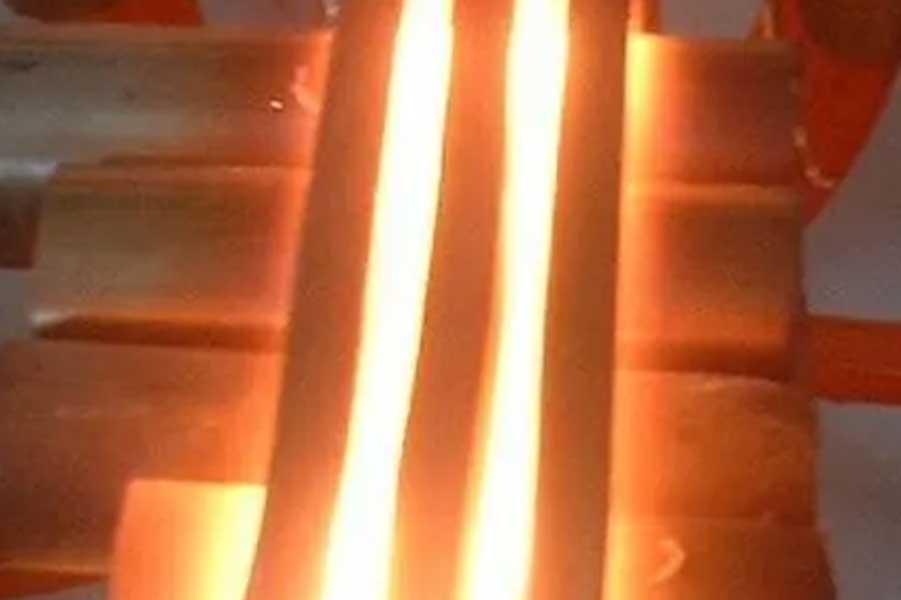
Due to sufficient heating and holding time, the depth and width of quenching and quenching cracks are slightly wider than that of surface quenching cracks, and due to the subsequent high temperature tempering heating, obvious oxidation and scale will appear in the unprotected atmosphere , the crack tail A short and thick tear-like morphology appears. Quenching and quenching cracks mostly extend along the circumferential direction, mostly near the end surface.
Surface induction hardening cracks are due to the short heating time, and the heat-affected zone is limited to the hardened layer area. The cracks produced are relatively shallow and fine, the tail is very sharp, and the distribution and extension direction are different from the quenched and tempered cracks. They are short in the hardened zone. There are more arc-like distributions, and the low temperature tempering after quenching is not enough to produce obvious oxidation and carbon depletion on both sides of the crack.
After investigation, the cause of quenching and quenching cracks is caused by improper quenching process. Because the quenching heating temperature is between 850 and 900 ℃, the temperature is relatively high, and then the quenching medium is rapidly cooled by the aqueous quenching cooling medium , and the structure transformation process Among them, the tear-like cracks produced after the local tensile stress is greater than the fracture strength of the material are one of the main reasons for the quenching and quenching cracks of the slewing bearing.
3. Conclusions and recommendations
1) After physical and chemical analysis, the bearings with quenched and tempered quenching cracks should be scrapped.
2) In quenching and tempering, selecting appropriate quenching process parameters can appropriately lower the quenching temperature and reduce the structural stress and thermal stress.
3) After quenching and tempering, a magnetic particle inspection process can be added to detect cracks in time to prevent unqualified products from entering the next process.
Link to this article: High quenching temperature, control of tearing cracks caused by water quenching and rapid cooling
Reprint Statement: If there are no special instructions, all articles on this site are original. Please indicate the source for reprinting:https://www.cncmachiningptj.com/,thanks!
 3, 4 and 5-axis precision CNC machining services for aluminum machining, beryllium, carbon steel, magnesium, titanium machining, Inconel, platinum, superalloy, acetal, polycarbonate, fiberglass, graphite and wood. Capable of machining parts up to 98 in. turning dia. and +/-0.001 in. straightness tolerance. Processes include milling, turning, drilling, boring, threading, tapping, forming, knurling, counterboring, countersinking, reaming and laser cutting. Secondary services such as assembly, centerless grinding, heat treating, plating and welding. Prototype and low to high volume production offered with maximum 50,000 units. Suitable for fluid power, pneumatics, hydraulics and valve applications. Serves the aerospace, aircraft, military, medical and defense industries.PTJ will strategize with you to provide the most cost-effective services to help you reach your target,Welcome to Contact us ( [email protected] ) directly for your new project.
Link to this article:High quenching temperature, control of tearing cracks caused by water quenching and rapid cooling
Reprint Statement: If there are no special instructions, all articles on this site are original. Please indicate the source for reprinting.:Cnc Machining,Thank!^^

