◆Basic requirements
Table of Contents
- 1. The machine tool should be assembled according to the drawings and assembly process. The parts of the machine tool must meet the quality requirements, all processed parts are not allowed to be hammered, and unspecified gaskets and sleeves must not be placed (in special circumstances, the designer must allow it), etc.
- 2. Parts and components during assembly should be cleaned and burrs removed. During the assembly process, there should be no bumps, scratches and rust on the machined surface of the workpiece, and the mating surface and exposed surface of the machined part should not have traces such as filing and polishing.
- 3. The end faces of the assembled bolts, screw heads and nuts should be evenly in contact with the plane of the parts to be fastened, and should not be inclined and left gaps. The length and type of the screws assembled in the same part should be the same. The tightened screws, nuts and bolts should not be loose, and the tightening force of the screws that affect the accuracy should be consistent.
- 4. After the nut is tightened, various stop rings should meet the braking requirements. If necessary, a part of low-strength, medium-strength glue can be applied to the threaded part to replace the stop ring
- 5. After the machine tool moves and the rotating parts are assembled, they should move smoothly, flexibly, lightly, without blocking, and the displacement mechanism should ensure accurate and reliable positioning.
- 6. The gap between the movable plate and fixed plate with a scale device on the machine tool should be about 0.2mm and the size should be uniform.
- 7. Check the radial and end runout of the shaft according to the technical requirements.
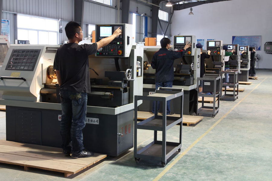
◆Assembly of components
- 1. Splines and parts with guiding flat keys and moving parts should move smoothly after being installed.
- 2. There should be no damage to the mating side of the flat key and the keyway. After the flat key is installed, the mating surface should evenly contact the keyway, and the two ends of the key are not allowed to tilt. The length of the taper pin in important parts shall not be less than 80% of the working length of the taper pin, and it shall be evenly distributed on both sides of the joint, and the large pieces shall be exposed on the surface of the workpiece by 2~3mm.
- 3. When assembling adjustable sliding bearings, there should be a proper clearance.
- 4. When installing a large bearing, the bearing and the shaft matching the bearing must be measured and the dimensional tolerance of the hole must be measured, and then it can be installed only after it meets the requirements.
- 5. When assembling the bearing, ensure that it is in place, the force is uniform, and there is no damage, and the contact between the bearing cap of the positioning end and the gasket or outer ring is even. After the inner ring of the bearing is assembled, it should be close to the shaft shoulder or distance ring.
- 6. When assembling bearings with interference fit by heating method, they should be heated evenly and the oil temperature should be below 150 degrees.
- 7. The edge of the oil groove of the sliding bearing should generally be blunt.
- 8. When assembling grease-lubricated bearings, an appropriate amount of grease should be added.
◆The installation of the pulley
- 1. The radial runout and end runout tolerance of the pulley on the shaft should meet the technical requirements.
- 2. The symmetrical center planes of the grooves of the two wheels coincide and are perpendicular to the axis of the pulley; the axes of the two wheels are parallel.
- 3. The belt tension is moderate, and there should be no obvious pulsation during transmission.
◆Sprocket installation
- 1. The axes of the two sprockets must be parallel.
- 2. The axial offset of the two sprockets should not be too large. Generally, the center distance of the two sprockets is less than 500mm, and the offset is less than 1mm. When it is greater than 500mm, the offset is less than 2mm.
- 3. The chain sag is appropriate.
◆Installation of gear
- 1. Coordination: There should be no eccentricity and skew on the fixed connecting gear, and there should be no seizure and blockage on the sliding gear.
- 2. Ensure that the gear has accurate center distance and proper backlash.
- 3. The axial misalignment amount of the toothed gear, when the width of the toothed gear rim is less than or equal to 20mm, shall not be greater than 1mm; when the width of the toothed gear rim is greater than 20mm, it shall not exceed 5% of the rim width and not more than 5mm .
- 4. Contact spots: For general transmission gears, the contact spots at the gear height are no less than 30%-50%, and the width is no less than 40%-70%. The distribution position is symmetrically distributed up and down at the pitch circle.
◆Worm drive
- 1. The axis of the worm shaft is perpendicular to the axis of the worm wheel.
- 2. The axis of the worm is in the symmetrical center plane of the worm gear teeth.
- 3. The center distance between the worm wheel and the worm is accurate, and there is a proper gap.
- 4. The worm drive is flexible, and there is no blockage during the rotation.
◆Screw drive
- 1. The axis of the screw and the axis of the nut are aligned with each other, and the axis of the screw is parallel to the trajectory of motion.
- 2. Ensure that the axial and radial clearance of the screw and the rotation accuracy of the screw meet the requirements.
- 3. The lead screw should be able to rotate flexibly, without blocking during the rotation.
◆Assembly of seal
- 1. Various seals assembled on the machine tool should not be damaged. Grease should be applied to the lips and surfaces of the seals and the shaft during assembly.
- 2. The assembling direction of the seal should be such that the working pressure of the medium presses its lip tightly on the shaft.
- 3. When assembling overlapping sealing rings, the rings should be pressed against each other, and the opening direction should be toward the side with higher pressure.
◆Assembly of transmission box
1. After the transmission box is assembled, the iron filings and debris in the box should be cleaned up, and cleaned after the empty vehicle test.
2. The test runs from low speed to high speed step by step, the running time of each speed shall not be less than 2min, and the speed shall not be less than 1h, and check the following items:
- A) The flexibility and reliability of the speed control mechanism;
- B) It runs smoothly, and there should be no abnormal screams and irregular impact noises;
- C) The oil circuit of the lubrication system should be unblocked and free of obstructions, and there should be no oil leakage at all parts;
- D) The radial runout and axial transmission of the spindle meet the inspection standards of the machine tool;
- E) When the spindle bearing reaches a stable temperature, its temperature and temperature rise should meet the technical regulations of various machine tools.
3. After the interlocking mechanism of the machine tool is assembled, its flexibility and reliability should be ensured.
4. The clutch and its control mechanism should have reliable coupling and disengagement performance.
◆Hydraulic lubrication part
- 1. There should be no leakage at all joints and exposed joints of the hydraulic system. Sealing ring packing or sealant is allowed to be used in joints and other joints, but hemp, silk and other sundries are not allowed to replace them.
- 2. The bend of the tubing should be lubricated, and the ratio of the short and long axis of the bent and flat tubing should not be less than 0.75.
- 3. Before assembling the hydraulic system, the joints, pipes, manifold blocks, solenoid valves, and oil cylinders should be cleaned.
- 4. Each valve body should act responsively and respond quickly. The movement sensitivity of the oil cylinder meets the technical requirements.
- 5. The pipeline setting should be safe and reasonable, arranged neatly, and convenient for component adjustment, repair and replacement.
- 6. The exposed port of the hydraulic system should be sealed with a sealing cap, and the external thread must be protected.
- 7. When installing the oil pump, pay attention to ensuring the coaxiality between the oil pump shaft and the drive motor drive shaft. The allowable error for rigid connection is 0.05mm, and the allowable error for flexible connection is 0.5mm.
- 8. The oil supply device of the intermittent lubrication system should have a stable intermittent period without interruption. The amount of oil delivered to each lubrication point through a quantitative distributor or an oil separator should be stable.
◆Guide part
- 1. The roughness and number of contact points of the scraped surface of all guide rails should meet the technical requirements.
- 2. The bonding surface of the application rail should be cleaned, and the bonding of the rail surface should be firm, and there should be no bubbles and voids. After the applied guide rail is cured, it should be processed according to relevant technical requirements, and the edge of the guide rail board should be chamfered and rounded.
- 3. There should be a margin for adjustment after the insert and the inclined iron are assembled.
- 4. The bottom surfaces of the two linear guides should be in the same plane and the reference surfaces on both sides should be parallel.
◆Appearance quality
- 1. The appearance of the machine tool should not have protrusions, depressions, roughness and other damages that are not specified in the design.
- 2. The protective cover of the machine tool should be flat and uniform, and should not be warped or sunken.
- 3. The surface of the welded part should be free of hammer marks, welded iron, metal spatter and arc ignition marks, and the edges and corners should be smooth. The slag of all welds should be cleaned up, and the appearance of welds should be polished smooth.
- 4. The edges of the exposed joint surfaces of machine parts and components should be neat and uniform, and there should be no obvious dislocation.
The door and cover of the machine tool and the joint surface of the machine tool should be attached, and the gap value of the attachment should not be greater than that specified in Table 1. The gap between the door and cover of the machine’s electrical cabinet, electrical box, etc. and its related documents should be uniform, and the uneven gap value should not be greater than the provisions in the following table.
- 1. The exposed weld seam should be trimmed straight and uniform.
- 2. The screw installed as a counterbore should not protrude from the surface of the part, and there should be no obvious eccentricity between its head and counterbore. The fixing pin should generally protrude slightly from the outer surface of the part, and the end of the bolt should protrude slightly from the end surface of the nut. , The exposed shaft end should protrude from the end face of the containing part, and the protruding value is about the chamfer value.
- 3. The surface of exposed parts of the machine tool should not be bumped or corroded. Screws, rivets, and pins must not be sprained or hammered.
- 4. The color of the plated parts, blue-haired parts and black-haired parts should be consistent, and the protective layer must not fade or fall off.
- 5. The exposed parts of the electrical, hydraulic, lubrication and cooling pipes should be arranged compactly and neatly arranged. If necessary, pipe clamps should be used to fix them. The pipes should not be twisted or folded.
◆Paint
- 1. The paint color and stripe ratio conform to the drawing standard of “Color Processing of Machine Tool Appearance”.
- 2. The paint layer of the machine tool must be beautiful, smooth in appearance, and uniform in color. The joints of the detachable assembly joint surface shall be cut after painting, and the edges shall not be dismantled when cutting.
- 3. No sagging, pitting, orange peel, whitening, bumps, scratches, and loss of gloss are allowed on the surface of the machine tool.
- 4. There are no traces of tape or butter on the bed.
- 5. There is no painting phenomenon on the surface of scraped grinding surface, guide rail, blue parts, screws, lead screws, chrome-plated parts, mating parts, and lubricating oil holes.
- 6. The paint layer on the joint surface of the component assembly must be clearly demarcated, and the edges and corners must be clear and neat.
- 7. The painting of various signs of the machine tool should be beautiful, clear and eye-catching. Paints of different colors must not contaminate each other.
- 8. Various signs on the machine tool should be clear and durable. The nameplate should be fixed in an obvious position, and the fixing position of the label should be correct, flat and firm, and not skewed.
Link to this article:General Technical Conditions For Machine Tool Installation
Reprint Statement: If there are no special instructions, all articles on this site are original. Please indicate the source for reprinting:https://www.cncmachiningptj.com/,thanks!
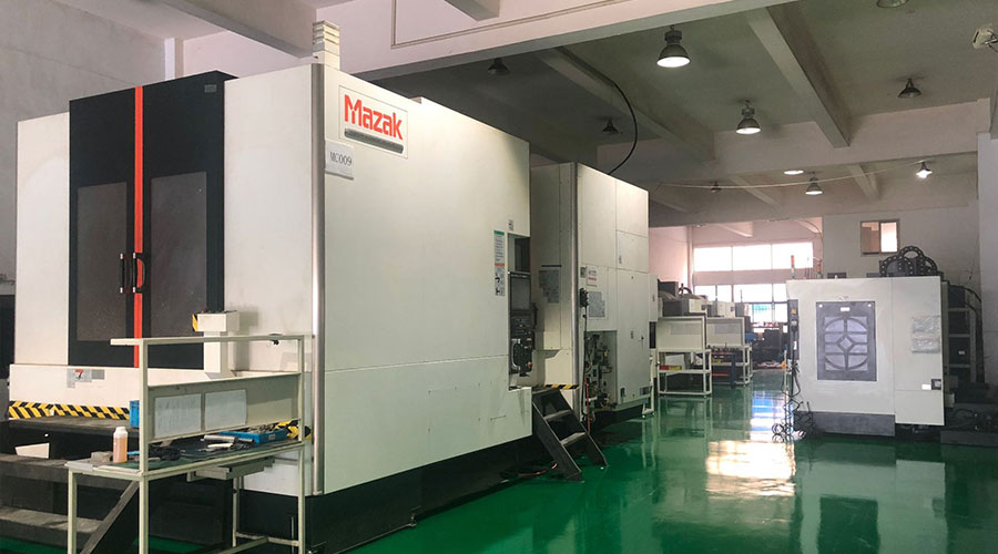 3, 4 and 5-axis precision CNC machining services for aluminum machining, beryllium, carbon steel, magnesium, titanium machining, Inconel, platinum, superalloy, acetal, polycarbonate, fiberglass, graphite and wood. Capable of machining parts up to 98 in. turning dia. and +/-0.001 in. straightness tolerance. Processes include milling, turning, drilling, boring, threading, tapping, forming, knurling, counterboring, countersinking, reaming and laser cutting. Secondary services such as assembly, centerless grinding, heat treating, plating and welding. Prototype and low to high volume production offered with maximum 50,000 units. Suitable for fluid power, pneumatics, hydraulics and valve applications. Serves the aerospace, aircraft, military, medical and defense industries.PTJ will strategize with you to provide the most cost-effective services to help you reach your target,Welcome to Contact us ( [email protected] ) directly for your new project.
Link to this article:General Technical Conditions For Machine Tool Installation
Reprint Statement: If there are no special instructions, all articles on this site are original. Please indicate the source for reprinting.:Cnc Machining,Thank!^^

