According to reports, the root cause of part defects is that the melt conveyed by the hot runner system is too hot. However, the true root is beyond my imagination.
The set point temperature of the temperature controller area is 480 o F, the actual temperature indicated is 480 o F, and it is stable (no fluctuation). However, the material is coming out of the export. The process technician, using a handheld device to measure the material purge temperature, reported that it was at 505 Ô F. Then, the technician used the handheld device and measured the purge temperature at 480 o F.
It is worth noting that the hot runner company did not provide temperature controllers and cables.
After further investigation
Table of Contents
The first thing to consider is whether the uninstalled thermocouple is misread. This situation is still a common problem and is worth checking. After checking and confirming that all thermocouples (t/c) were properly in place to “read” the steel temperature instead of the air temperature, the technician replaced the hot runner temperature controller and used a new power cord and t/c cable To test the mold. Now the set temperature is 480 o F, the actual temperature is 480 o F, and the purge temperature is 480 o F, thus eliminating the part wire drawing. Although this solved the part problem, it did not reveal the root cause.
Because molders have invested too much money in the current temperature controller, they are reluctant to make changes, but we have conducted more in-depth research. First, we automatically adjusted the existing temperature controller. However, when the set point temperature is 480 Ó F, the actual temperature (displayed) is 480 ö F and non-variable, but the melting temperature is 505 ö F.
This is not an automatic adjustment of the temperature controller. The hot runner system works as expected with another temperature controller/cable setting, proving that it is not the thermocouple placement/contact of the hot runner system. This also proves that it is not the hot runner system junction box on the mold or the existing temperature controller. We infer that this must be the thermocouple cable and/or the plug/socket pin contact is not good, this is a common problem. However, in this case, the plug or socket is obviously not a problem.
Next, we consider cables. Usually, the thermocouple wire will be K-type instead of the required J-type, but this is not the case here. Because we did find that the molding machine uses copper wire.
Unexpectedly (for me), the molder was not shocked. Instead, they stated that they always use copper wire instead of thermocouple wire, and the mold maker that runs the trial mold also uses copper wire. They don’t want to spend extra on t/c cables, and they have been doing this for so many years without any problems. At this point, we can be sure that molders are not aware that they are experiencing problems that may cause part defects.
Most importantly, for any molding applications, especially those with “technical” parts and materials, copper cables should not be used to monitor the thermocouple’s feedback to the temperature controller.
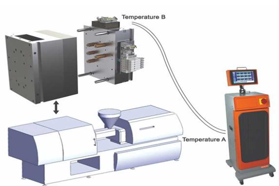
Schematic diagram explaining why copper wire cables should not be used: the air temperature (temperature B) of the mold electrical junction box (inside) = 100°F; the air temperature of the controller (temperature A) = 75°F; the set point is 480° F.
Copper-free cable
This is an example of why stores should not use copper cables to monitor the feedback of thermocouples to temperature controllers (see the sidebar for definitions and diagrams):
The air temperature (temperature B) of the electrical junction box (inside) of the mold: 100°F
Controller’s air temperature (temperature A): 75°F
Set point: 480°F
Use a correctly wired thermocouple (J or K type) extension cord
If the hot end is 480°F, the analog input (AI) terminal is 75°F, and for any t/c type, the electromotive force (EMF) can be seen at AI, then PV = 480°F-75°F + 77°F = 482°F. When t/c wired cables are used as needed, the temperature of the mold electrical junction box will increase by a “zero” unknown error. Note: The temperature controller needs a fan-cooled enclosure.
When using copper extension cords, the PV equation remains unchanged, plus an “error” unknown to the operator (or temperature controller). Since the PV equation remains unchanged, the actual temperature indicated by the temperature controller also remains unchanged. What does exist but not pointed out is the “error”, which is the actual temperature of the t/c tip, which is the additional “error” heat of the plastic.
If the hot end is 480°F, the AI junction box is 75°F, and the “visible” EMF on the AI is (static), then PV = 480°F-75°F + 77°F = 482°F. However, when copper wire is used, another node added does not belong to the temperature controller logic. The error is not visually displayed on the controller.
t / c-the temperature of the copper junction is 100°F (temperature B): temperature B (100°F)-temperature A (75°F) = 25°F. The actual actual temperature of the thermocouple tip is the actual temperature of the melt at 505°F.
Again, the actual temperature is 505°F because you cannot use the cold junction or the other end to program the temperature controller. The user has no way of knowing this, so the indicated/actual temperature reading on the controller is regarded as good news. For example, the material in this example is 25°F higher than the temperature indicated on the temperature controller reading.
Similarly, the internal temperature of the mold junction box mounted on the top of the mold may exceed 100°F, especially in certain areas in summer. These temperatures will increase and decrease unknown errors relative to the time of day and season, which may affect the temperature of the workshop during the day or night.
Glossary
Hot end: The area where the tip of the thermocouple touches the manifold and/or nozzle. Note: The tip is the only position the thermocouple senses.
AI (analog input) terminal block: the terminal block in the temperature controller cabinet.
Temperature A: It is important to cool the temperature controller cabinet with an electric fan.
Temperature B: The air temperature in the electrical box where the mold is installed.
Cold junction compensation: A fixed offset temperature programmed in the logic of the temperature controller, usually 77°F (25°C).
EMF: electromotive force; the electric potential difference between two points.
Thermocouple (t/c): A device that converts temperature into a physical quantity of voltage or resistance and provides the output.
Mold electrical junction box: experiencing “temperature B” (heat rise).
Set point: The user enters the temperature setting required by the temperature controller.
Present value (PV): Also called the actual temperature reading indicated, but not when copper wire cable is used instead of thermocouple wire cable.
The programming of the temperature controller is as follows:
PV: The temperature of the tip of the thermocouple (-) temperature A (+) cold junction compensation. The additional junction error is temperature B (+/-) (the temperature controller cannot recognize this error).
Increased junction error: The increased junction error caused by the use of copper wire instead of thermocouple wire. The error is equal to temperature B temperature.
Link to this article: Analysis of temperature troubleshooting methods for hot runner controllers!
Reprint Statement: If there are no special instructions, all articles on this site are original. Please indicate the source for reprinting:https://www.cncmachiningptj.com/,thanks!
 Sheet metal, beryllium, carbon steel, magnesium, 3D printing, precision CNC machining services for heavy equipment, construction, agriculture and hydraulic industries. Suitable for plastics and rare alloys machining. It can turn parts up to 15.7 inches in diameter. Processes include swiss machining,broaching, turning, milling, boring and threading. It also provides metal polishing, painting, surface grinding and shaft straightening services. The production range is up to 50,000 pieces. Suitable for screw, coupling, bearing, pump, gearbox housing, drum dryer and rotary feed valve applications.PTJ will strategize with you to provide the most cost-effective services to help you reach your target,Welcome to Contact us ( [email protected] ) directly for your new project.
Link to this article:Analysis of temperature troubleshooting methods for hot runner controllers!
Reprint Statement: If there are no special instructions, all articles on this site are original. Please indicate the source for reprinting.:Cnc Machining,Thank!^^

