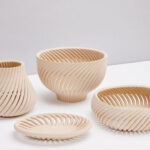
Additional tools refer to the use of 3D printing (such as direct metal laser sintering or DMLS) to produce mold inserts from metal, which will be used to produce large quantities of 101 molds. The additive manufacturing tool also includes a sub-insert, which can be inserted into a larger mold or mold base, slide rail, ejector pin, gate insert, and finally forms a plastic template cavity. Additive manufacturing tools can distinguish high-volume, durable Class 101 tools from simple 3D printed resin tools for prototyping.
The core of additive mold design is the opposite of mold construction. For example, many common CAD modeling functions are designed around milling and drilling. Therefore, traditional mold manufacturing starts with a steel billet, and the required material is cut from the billet to achieve the final shape. Instead, material is actually added to form the shape of the tool needed to produce the part from the mold.
This change of thinking will change the way the factory designs molds, wire cooling circuits, provide clearances and finishing machines, and simplify the entire workflow from design to mold construction.
Create creativity through heat dissipation design
Table of Contents
Conformal cooling is common in mold manufacturing. The main driving force of conformal cooling is the ability of the cooling circuit to follow the contour of the plastic cavity surface to produce a consistent cooling effect. Another driving factor is the injection of water into places where conventional milling and drilling are not allowed. However, both of these benefits require creativity in creating complex contours, avoiding dead ends, and promoting turbulence.
Conformal cooling is still the primary application of additive manufacturing in mold manufacturing, that is, conformal cooling 3D printed mold inserts or additive molds. Many mold makers have adopted additive manufacturing tools to differentiate their mold performance from competitors, but many designers insist on subtractive thinking. Therefore, although the cross-drilled waterline plug is eliminated, the cooling circuit still appears Very traditional. This is the highlight of the additional tool, because it can achieve unlimited design constraints. However, conformal cooling is a delicate balance between creativity and convention. Conventional mold design standards are still important to maintain design discipline to create efficient cooling circuits.
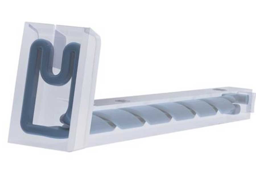
For example, to maintain a consistent cooling effect on the entire mold surface, keep the cooling circuit at a certain distance. It is important to note that cold spots may appear in the mold, just like hot spots, which may have a negative impact on the molding performance. Consistency is the key.
When using circuit profiles, things start to get interesting because many options are provided to promote greater surface area and turbulence. Some profiles have internal grooves to maximize surface area, while others have spiral ramps to promote turbulence.
Most of these designs do not consider the construction process and create functional parts that need to be supported. These supporting parts may limit the flow of the cooling circuit or form sharp corners where concentrated stress may cause cracks. An elliptical or elongated cooling circuit is the best choice for maximum flow, enabling the best heat transfer and squeezing between narrow steel sections that require maximum cooling.
A controversial cooling circuit design is to divide the circuit into several smaller channels and deliver the larger circuit to them from the mold. For example, a good way to minimize the number of loops in a mold is to use a large inlet (1/4 inch or 1/3 inch NPT waterline), you can divide it into multiple waterlines, and then reconnect at the outlet connect.
However, with this design, the circuit may be blocked and undetectable until the molder produces a defective part. When using a single circuit, you can easily monitor the input and output flow and quickly determine the problem.
Another consideration when using multiple production lines is that the DMLS powder enters the production line after construction. Because there are multiple production lines, it is difficult to determine whether to evacuate all the powder before heat treatment. If the powder gets stuck in the circuit, the shop must scrape off the plug-in. By limiting the segmentation to less than one-third of the total loop length, the risk of internal segmentation waterlines can be reduced. This rule of thumb helps to maintain a large flow rate and then only separate the circuit at the required critical locations, so that the powder can be evacuated without the risk of clogging.
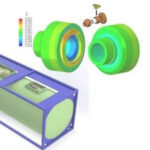
After having the best circuit design, conduct a cooling simulation study to confirm its effectiveness, and then run an FEA analysis to confirm the integrity of the insert and the steel conditions sufficient to withstand the injection pressure. Using this method for circuit design can determine the most suitable solution for mold design before manufacturing the insert.
Maximize clearance to minimize processing
Using additional mindsets helps to accurately determine what is needed to form the details of the shape of the part, while eliminating the material in the remaining blades, thereby reducing costs and avoiding secondary processing. However, although the surface properties produced by most 3D printing processes are sufficient to meet the needs of the cooling channels, they cannot produce the necessary surface finish. In order to overcome this limitation, processing materials can be added to the CAD model, and oversized parts can be constructed to finish the parts to precision tolerances.
Mold manufacturers usually increase the gap between two pieces of steel to minimize wear, improve ventilation, reduce heat transfer, or assist in mold assembly and disassembly. You can achieve each of the above advantages by 3D printing complex gaps (instead of traditional milling or drilling), with additional tools.
For example, the core or cavity insert in the core releases about 60% on the mating surface. Additive manufacturing of the blade and then finishing the remaining 40% of the mating surface will reduce machining time and cutting tool wear.
Adding processing materials to the shape of the part only requires finishing, or EDM on the surface of the cavity, thereby eliminating the work of roughing, stress relief, EDM drilling and roughing electrodes. Compared with conventional machining using billet, this method can reduce electrode machining and burning time by 50%.
Use software to simplify the workflow of additional tools
Software plays an important role in simplifying or automating mold design and manufacturing. The additional tools are no different because a lot of time is spent on designing the cooling circuit. Today’s software tools for additive manufacturing (such as Netfabb and nTop) provide dedicated conformal cooling design features that simplify the design process and reduce circuit design time. This simplified process allows the design to enter the simulation process faster, thus confirming the validity before 3D printing the plug-in.
Today’s additive software provides confidence in the successful construction of additive tools by checking the printability of the part, automating the support structure and simulating the part to identify potential stress or deformation areas and optimize them as needed.
Link to this article: How to use additional tools to design molds?
Reprint Statement: If there are no special instructions, all articles on this site are original. Please indicate the source for reprinting:https://www.cncmachiningptj.com/,thanks!
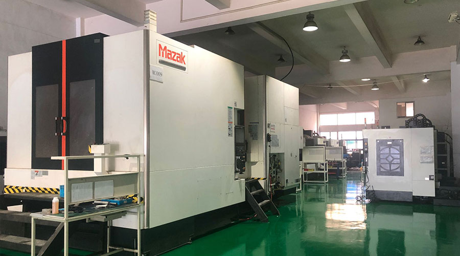 Sheet metal, beryllium, carbon steel, magnesium, 3D printing, precision CNC machining services for heavy equipment, construction, agriculture and hydraulic industries. Suitable for plastics and rare alloys machining. It can turn parts up to 15.7 inches in diameter. Processes include swiss machining,broaching, turning, milling, boring and threading. It also provides metal polishing, painting, surface grinding and shaft straightening services. The production range is up to 50,000 pieces. Suitable for screw, coupling, bearing, pump, gearbox housing, drum dryer and rotary feed valve applications.PTJ will strategize with you to provide the most cost-effective services to help you reach your target,Welcome to Contact us ( [email protected] ) directly for your new project.
Link to this article:How to use additional tools to design molds?
Reprint Statement: If there are no special instructions, all articles on this site are original. Please indicate the source for reprinting.:Cnc Machining,Thank!^^

