The blown film industry has developed from a single-layer film structure to a multi-layer film structure for various food and non-food packaging applications. According to the requirements of the product, a variety of materials can be integrated into the film structure to obtain the required performance.
Process engineers working in this field must have a basic understanding of polymer rheology in order to correctly specify equipment and select process conditions. If the properties of the polymer are not fully understood, unnecessary interlayer interactions may occur during processing, which may lead to defects in the film.
Rheology is the study of material deformation and flow. The degree of deformation and flow experienced by the material depends on its rheology. For polymers, these properties depend on physical properties such as molecular weight (MW), molecular weight distribution (MWD), long chain branching (LCB), and melting temperature. In blown film coextrusion, the most important rheological properties to consider are shear viscosity, viscous dissipation and elongational viscosity.
Shear viscosity is a measure of the resistance of a material to shear flow and is affected by shear stress and shear rate. Shear stress is defined as the force per unit area exerted on the material, and the shear rate is defined as the rate of deformation of the material.
The polymer is a non-Newtonian fluid, so its viscosity will not remain constant when the shear rate changes. Generally, the shear viscosity of the polymer will decrease as the shear rate increases. This behavior is called shear thinning. The rate of shear thinning of a polymer determines how it is processed. For example, highly branched polymers are more sensitive to shear than linear polymers, and therefore, at higher shear rates, the shear viscosity will decrease more quickly. Processing highly viscous materials will cause the melt temperature to rise, the pressure head to rise, and more extruders to apply torque.
When a polymer is sheared, the chain entanglements within its molecular structure begin to unravel. This unwrapping process generates heat, and this phenomenon is called viscous dissipation. Viscous dissipation is proportional to both the applied shear rate and polymer viscosity, which means that an increase in polymer viscosity and/or shear rate will result in an increase in melt temperature. This phenomenon creates a temperature gradient between the extruder barrel and the melt. Without proper consideration, an increase in the melting temperature may cause the polymer to overheat and degrade.
The elongational viscosity is defined as the stretch resistance of the material. Similar to shear viscosity, the elongational viscosity of a polymer will depend on its molecular structure. A polymer with a high degree of LCB will have a high elongational viscosity because the long branches are entangled with each other during the elongation process. The maximum tension that can be applied to the melt without material fracture is called melt strength. A material with a higher elongational viscosity will have a higher melt strength. The melt strength of the polymer will affect the stability of the bubbles formed in blown film extrusion. A material with lower melt strength is more difficult to process because it breaks more easily when stretched during bubble formation.
Common problems and troubleshooting techniques
Table of Contents
Although the production of multilayer films is advantageous and provides opportunities for improving film performance, the increased structural complexity presents new challenges for process engineers. In order to successfully produce multilayer films, four key factors must be considered: 1) polymer selection, 2) process equipment design, 3) layer arrangement and 4) process conditions. When one or more of these factors is not fully considered, the problem of blown film co-extrusion will occur. Five common problems related to blown film coextrusion and troubleshooting techniques for each problem will be detailed below.
1. Bubble instability :
The term “bubble instability” covers many issues related to the stability of extruded bubbles. The main problems include bubble bursting, strain hardening, unstable frost lines, and bubble vibration.
Bubble rupture: When the molten material leaving the mold is overstretched, the bubble rupture will occur, resulting in the rupture of the bubble structure. This happens when the melt strength of the extruded material is insufficient to reach the selected blow-up ratio (BUR). To avoid this problem, the choice of resin can be modified to incorporate higher melt strength materials into the film structure to increase the overall melt strength. An example of this is the incorporation of low density polyethylene (LDPE) into linear low density polyethylene (LLDPE) film to increase its overall melt strength.
Strain hardening: Strain hardening occurs when the molten polymer is rapidly stretched in the machine direction (MD) and thus hardens. This causes fluctuations in internal bubble pressure and bubble width. This problem can be avoided by reducing the retracement rate. Another solution is to change the choice of resin to reduce the overall elongational viscosity of the film, allowing the film to stretch more in MD without any strain hardening.
Unstable frost line: In the stable process, the frost line will remain at a constant height above the mold and is controlled by the cooling rate, mold output and film thickness uniformity. When the process becomes unstable, the position of the frost line also becomes unstable. One reason for this instability is the uneven temperature distribution in the extrudate.
Changes in melt temperature may be due to incorrect screw design of the selected resin, screw wear, or heater or thermocouple failure. Before merging, the melt temperature should be obtained for each stream to determine which melt layer is the source of the temperature change. Once positioned, the screws can be removed and checked for degradation of the polymer and wear of the screws. The function of all heaters and thermocouples should also be checked.
Another common cause of unstable frost line is mold clogging. Uneven mold throughput may be caused by the accumulation of degraded materials in the mold. In order to avoid this situation, the mold should be regularly checked for material accumulation and cleaned if necessary.
Bubble fluttering: The bubble fluttering starts below the frost line and is displayed as a linear mark in the transverse direction (TD) of the bubble surface. This vibration is caused by the high air velocity from the air ring. Reducing the blower speed or adjusting the air ring assembly to reduce the air flow along the bubble surface will prevent the bubbles from floating. However, reducing the air flow will subsequently reduce the cooling efficiency of the air ring, which may cause the frost line to be removed from the mold, causing new problems. To avoid this, the resin selection can be optimized to reduce the total melt viscosity of the extrudate and lower the total melt temperature.
2. Specification change :
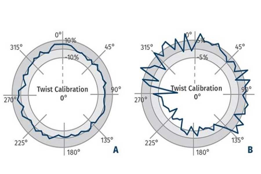
In blown film coextrusion, it is inevitable that there will be some degree of specification change in the film (usually in TD). An example of the gauge profile of a film with a low degree of gauge variation can be seen in Figure 1a. However, if unexpected problems start to occur during processing, the degree of specification deviation will increase. There are a number of different problems that may cause an increase in meter variation, and the cause of the problem can be determined by checking the shape of the bubble’s meter profile.
Mold misalignment: A common source of specification deviation is mold gap misalignment. Misalignment of the mold can cause uneven distribution of material leaving the mold. A common indicator of mold misalignment is the offset gauge profile, as shown in Figure 1b. To correct this problem, check the uniformity of the mold gap along the circumference. If it is not aligned, you can use the mold adjustment bolts to reposition the mold.
Figure 1 An example of a scale chart of a film sample undergoing the following conditions: A) minimum scale change; B) offset gauge change.
Uneven air ring cooling: Poor air flow or uneven air flow in the air ring will cause uneven cooling of the film, which will affect the stretch ratio of the film. This may cause parts of the film to be stretched more than other parts, which may cause specification changes. To avoid this problem, the air passage in the air ring should be checked and cleaned regularly to remove all impurities that may cause airflow interference. The air ring should also be checked to ensure it is properly centered on the mold.
Uneven melt temperature: Uneven melt temperature will cause changes in bubble cooling rate and die output. An obvious sign of uneven melt temperature is the sinusoidal gauge curve. The formation of this sinusoidal gauge change is related to the flow of materials with uneven melt temperature through the mold. This phenomenon is called port line. As mentioned earlier, the change in melt temperature is likely to be caused by improper screw design or wear.
3. Interface instability :
The term interface instability refers to the instability that occurs at the interface between two layers. The stability of the interface will depend on factors such as material properties, process conditions, and equipment design features. Three known types of interfacial instability may occur during blown film coextrusion.
Zigzag interface instability: When the interface is subjected to excessive shear stress, this form of instability will appear, which will result in a “zigzag” deformation on the film surface along the TD direction. The image of this instability is shown in Figure
There are some known causes of zigzag instability. The first is the difference in shear viscosity between the materials that produce the interface. If the material has significantly different shear viscosities, the various layers will experience different shear rates under the applied shear stress, resulting in zigzag deformation. This can be alleviated by choosing materials with similar shear viscosity (if possible) to create the interface.
The second reason is that the layer ratio is inappropriate. If the layer ratio is selected so that the interface is too close to the mold wall, excessive shear stress will trigger deformation. To prevent this, the thickness of the outer layer can be increased to move the interface away from the wall and reduce the shear stress applied to the wall.
The third reason is improper mold design. When designing a mold, it is important to properly optimize the fluid channels to create a uniform velocity distribution throughout the mold. Improper mold design may result in high shear points and uneven velocity distribution, which can lead to this instability.
Wave interface instability: This form of instability is caused by uneven elongation deformation at the interface between the two materials. When the bubble is extruded from the mold, it will form a wave shape along the bubble surface pattern. An image of this instability can be seen in Figure 3. It has been found that the elongation deformation that causes this instability occurs from two known sources. The first one is related to the inappropriate layer ratio. If one of the combined layers of the structure is too thin, it will experience greater acceleration at the merging point in the mold, resulting in a higher elongation deformation rate in that layer. The ratio of the layers should be adjusted to allow a more uniform velocity distribution downstream of the merge point.
The second source is the difference in the elongational viscosity of the materials that make up the interface. Two materials with different elongational viscosities will experience the same elongation force, and they will deform at different rates. If possible, materials with similar elongation properties should be selected to create the interface.
Reactive interface instability: When co-extruding a multilayer structure composed of a polar barrier resin and an adhesive layer, a reactive interface may be formed. The barrier resin is usually co-extruded with the polyolefin resin layer. These structures usually require a bonding layer between them to improve the adhesion between them. The bonding layer is a polymer composed of polar and non-polar end groups. Sometimes, an unwanted chemical reaction may occur between the polar end groups of the adhesive layer and the polar barrier resin, thereby forming an unstable interface. The result of these reactions is to reduce the optical clarity and give the film a rougher appearance.
An example of this instability is the interface between EVOH and a tie layer with maleic anhydride (MA) functional groups. Unwanted reactions may occur between the MA of the tie layer and the hydroxyl groups along the EVOH chain. A visual example of this instability is shown in Figure 4, which compares PP/EVOH multilayer films co-extruded under the same conditions without an adhesive layer (Figure 4a) and an MA adhesive layer (Figure 4b) . Due to the undesirable interaction occurring at the interface between the EVOH and the MA bonding layer, the addition of the MA bonding layer resulted in a sharp decline in the clarity of the optical film. In order to prevent this from happening, the connection layer can be replaced by a connection layer composed of different functional end groups.
4. Gel :
The term “gel” is generally used to refer to any form of small defects that will produce optical distortions in the final film. Gels are problematic because they not only cause optical distortion, but also reduce the mechanical properties of the film. Gels can be divided into three categories: unmelted resin, degraded materials and foreign contaminants.
Unmelted resin: Unmelted resin is a common type of gel, which can usually be observed under high extruder throughput. They are the result of uneven melting caused by the low shear zone located in the extruder. To determine whether the gel is unmelted resin, heat the gel above its melting temperature and then allow it to cool down. If the gel does not reappear after cooling, it is an unmelted resin. If there is unmelted resin in the film, the extruder screw should be checked and redesigned to minimize the presence of low shear zones.
Degraded material: If the polymer is exposed to high energy for a long time, material degradation will occur during the extrusion process. These conditions result in the formation of highly oxidized or cross-linked materials, which appear as gels in the film. Usually, these gels do not exist immediately after start-up. Over time, they will appear on the film because the degraded polymer will accumulate in the process.
Highly oxidized gel appears as brittle black spots, which can be identified by fluorescence under ultraviolet light. Figure 5 shows an image of a highly oxidized gel obtained under polarized light, and an image of gel fluorescence obtained under UV light. The cross-linked gel has a dark brown appearance and is composed of oxidized substances, but the degree of oxidation is too low to cause fluorescence under ultraviolet light.
Crosslinked gels are sometimes mistaken for highly entangled resins. To distinguish between the two, the gel is heated above its melting temperature, stress is applied to it to break it, and then it is allowed to cool. If the gel shape reappears after cooling, it indicates that the material is cross-linked and not highly entangled. In order to determine the source of degraded materials, the extruder screw should be removed without purging after operation. Once the source of degradation is identified, the screw design can be optimized in this area to minimize stagnation and low shear.
Foreign contaminants: Sometimes, foreign contaminants may enter the process. Foreign contaminants usually enter the extruder through a hopper together with the main raw materials, and can range from clothing fibers to foreign polymer resins. If it is found that the melting temperature of the gel is significantly different from the melting temperature of the raw resin, or its shape is very irregular (such as fibrils), it is likely to be foreign contaminants. To avoid these gels, the hopper should always be properly cleaned and the original raw material container should be sealed to prevent any foreign matter from getting in.
5. Film curling :
Film curling is a defect observed in a multilayer structure composed of materials with different crystallinity. This defect is formed during the cooling of the molten film and causes the film to roll up on itself. Film curling is related to two problems: differences in material properties (ie, melting point, crystallinity) and improper layer arrangement.
A common example of film curling is shown in Figure 6, which shows a three-layer film composed of polyethylene (PE), nylon (PA) and an adhesive layer. When the multilayer film leaves the mold, all the layers melt and the film begins to cool. As it cools, the nylon layer crystallizes and becomes hard, while the PE layer shrinks while still in the molten state. Once the temperature drops below the melting temperature of PE, it will also start to become hard. However, at this time the nylon has crystallized and cannot shrink further, causing the PE to curl from it during the curing process.
One way to prevent film curling is to cool the film quickly to prevent crystallization. In contrast to using air to cool the film, the film can be extruded directly into a water bath for rapid cooling. This allows materials with different crystallization rates to be co-extruded without any curling of the film. Another possible solution is to optimize the structure of the multilayer film.
For example, modify the structure of a PE/tie/PA film that may be curled to PE/tie/PA/tie/PE/tie/PA. The additional layers in the new film increase the overall quality of the film, which will reduce the degree of curl experienced by the film.
Link to this article: What are the common problems in the coextrusion blown film process?
Reprint Statement: If there are no special instructions, all articles on this site are original. Please indicate the source for reprinting:https://www.cncmachiningptj.com/,thanks!
 3, 4 and 5-axis precision CNC machining services for aluminum machining, beryllium, carbon steel, magnesium, titanium machining, Inconel, platinum, superalloy, acetal, polycarbonate, fiberglass, graphite and wood. Capable of machining parts up to 98 in. turning dia. and +/-0.001 in. straightness tolerance. Processes include milling, turning, drilling, boring, threading, tapping, forming, knurling, counterboring, countersinking, reaming and laser cutting. Secondary services such as assembly, centerless grinding, heat treating, plating and welding. Prototype and low to high volume production offered with maximum 50,000 units. Suitable for fluid power, pneumatics, hydraulics and valve applications. Serves the aerospace, aircraft, military, medical and defense industries.PTJ will strategize with you to provide the most cost-effective services to help you reach your target,Welcome to Contact us ( [email protected] ) directly for your new project.
Link to this article:What are the common problems in the coextrusion blown film process?
Reprint Statement: If there are no special instructions, all articles on this site are original. Please indicate the source for reprinting.:Cnc Machining,Thank!^^

